Rounding Things In Tinkercad
Overview
A Guide To Rounding Corners and Edges in Tinkercad.
Alternately, how I spent way too much time modeling a dice tray.
Rounding corners in Tinkercad is way more trouble than it ought to be. It’s not actually hard, it’s just really time consuming and requires a lot of steps. Once you wrap your head around the general approach you’ll be able to round anything.
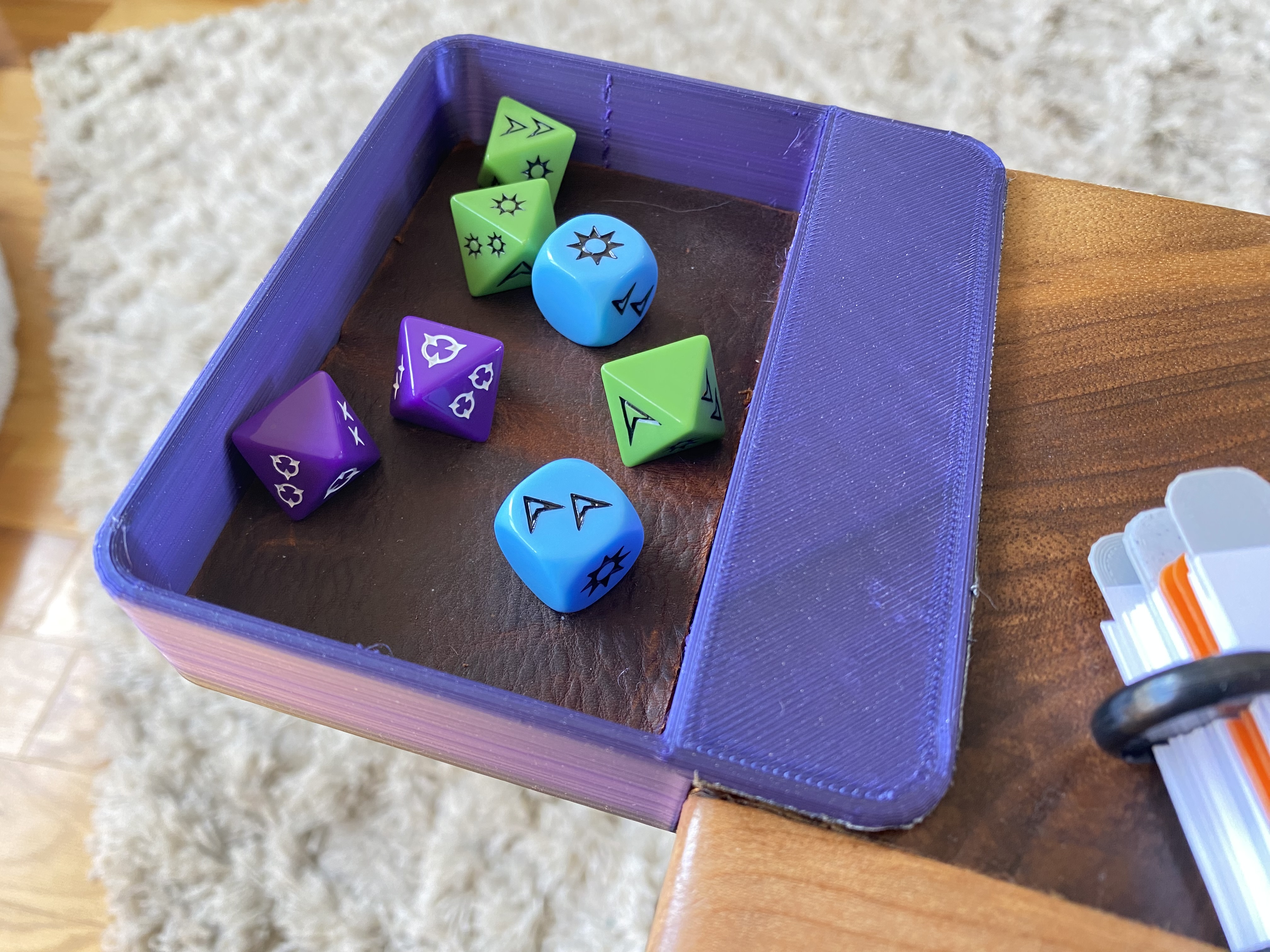
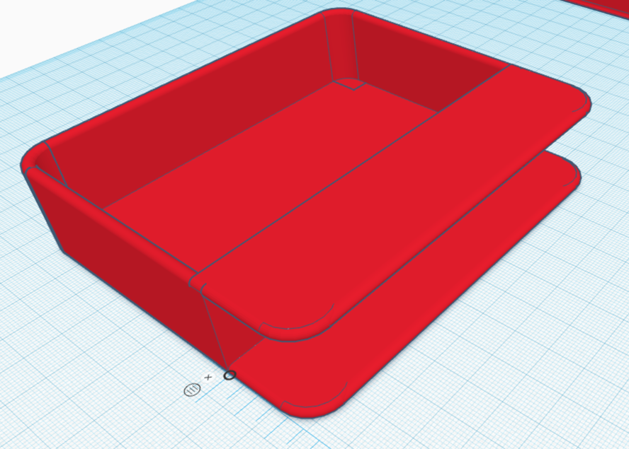
This post will take you through the steps required to round the and edges on this simple dice tray.
Step-By-Step
High level rounding:
In most case you can simply stick a rounded thing on top of a rectangular thing and that’s it. For example, most of the walls in this are simply rectangles with half-cylinders laid lengthwise on top of them. That’s the bit you probably don’t need help with.
When you can’t simply build the shape you want, but instead need to round off an existing corner the approach is actually fairly similar. You build up the shape of the cut, cut it out of something, and then turn that something into a “hole”. For example: this image shows the sequence of things I’d do to round off one edge of a cube. I take a cylinder, which has the rounded shape I want, then cut it out of a another cube or rectilinear shape that is at least as large as the thing I want to round off. Then I convert that shape into a whole, and use it to cut off the edge of the cube.
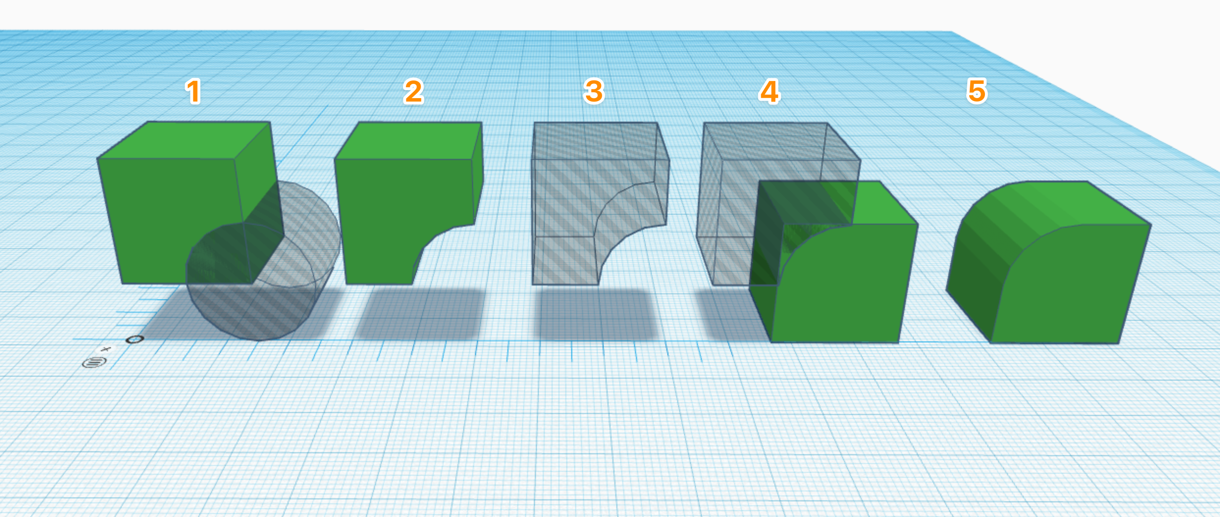
Pro-tip. Make the thing that will be your cutting tool an even multiple of the size you’re cutting out of it. For example. The cylinder is 10mm into the cube I’m going to cut. The cube is 20mm wide. This means that when I use the resulting hole to cut into other shapes I can simply overlap them by 10mm.
The Corners
The corners are the most complicated part of this build. In order to have them curve over the edge on the top, but be flat on the bottom I needed to create a cylinder with rounded edges that were different on each end.
To build the bottom of the corner we take a torus (donut) and stick it on top of a cylinder. It’s much easier to build this upside down and then rotate it.
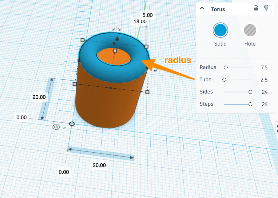
Note that the “Tube” slider controls the radius of the curved cylinder that makes up a torus shape. Your life will be significantly easier if you can make this a whole number. I wanted a 3mm wide wall, so I used a 1.5mm “Tube” which just made all the future placements of objects much more difficult. If I was doing it again, I’d just make the wall 4mm thick. Change the “tube” setting to be the size you want, then deal with the outer dimensions. Changing the tube radius alters the outer dimensions, so there’s no point in setting those first.
For the bottom we need to add a cylinder that fills the area from the top of each rounded side of the torus. This means we need a cylinder that is the diameter of the outer cylinder, minus the radius of your “tube” times 4. Set a ruler at the corner of the initial cylinder to help you place this inner cylinder correctly. The inner cylinder will be the height of the initial cylinder plus 1x the radius of your “tube”.
So, if we have a torus that with a 2mm tube (radius), and it sits on a cylinder that is 20mm in diameter, and 20mm high, then your inner cylinder will be 16mm in diameter and 22mm tall. To position the inner cylinder move it 2mm towards the center along the X and Y axis.
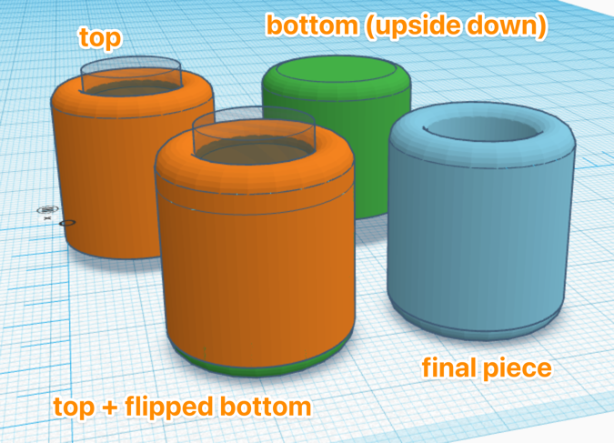
This picture shows the bottom of our corner with the pieces put together, and with the center cylinder offset. Now Shorten the outer and inner cylinders by at least the radius of your tube, and then shift them back up into position. Copy this shape, and set it aside, so that we can use it as the start of our top corner. Then group these pieces, and rotate it 180° to form a nice flat bottom with rounded edges, and drop it down so that it touches the ground.
Take the copy you set aside, and change the diameter of the inner cylinder by subtracting 4x the radius of the tube. Now it’s 12mm in diameter, and should look like it’s poking through the center of your torus. Convert that center cylinder to a hole. Now, shorten your cylinder by the radius of the torus. Then shift it up so that it’s touching your top torus, and hovering above the ground. and then combine all the pieces of the top here except for the hole. Make sure the bottom and top have different colors so that you can better see what’s happening in the next step.
Bonus points: If you want the inner curve at the bottom to be rounded too, add a half-sphere on top of your hole cylinder, combine them, and rotate it. Make sure that the bottom (the tip of the half-sphere) is the thickness of your floor away from the ground.
Combine the top and bottom pieces, then group everything. The process should look like this.
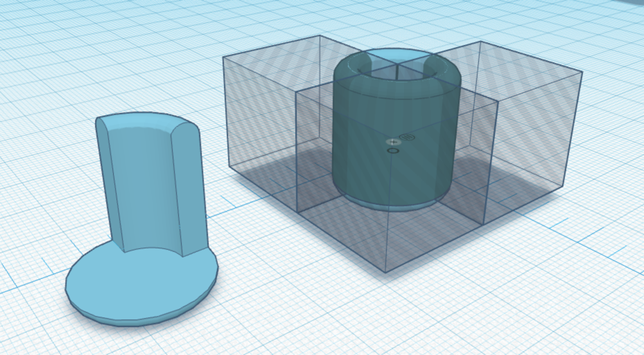
The next step is to cut away the excess and make it into a corner piece. For this I just take 3 cube holes. Each cube should be 2x the diameter of your cylinder. Arrange them so that they all intersect at the center of your cylinder, and are raised up the radius of your “tube”. Then combine all the shapes. Here’s the before and after.
Now we’ve got our corner piece.
You’re past the hardest part.
The “ears”
There are a couple ways to address this. You can take a rectangle, and attach 3 half cylinders of the appropriate size to the edges. I wasn’t so smart. I built the thing with rectangles and then cut away pieces.
Sooner or later though, you won’t be able to do this, and you’ll need to round off something as shows in the earlier sequence.
The thing worth copying here is the rounded corners. To make these you simple create a disk. This is just like creating the bottom of the corner, except that the height of the inner cylinder is 2x the “tube” radius of the torus it’s going inside. Combine those and you’ve got a disc with rounded corners. The torus you start with should have a diameter equal to the thickness of the thing you’re rounding.
Chop off a square corner from the item where the disk, then slide the disk into place, and combine the things.
Everything Else
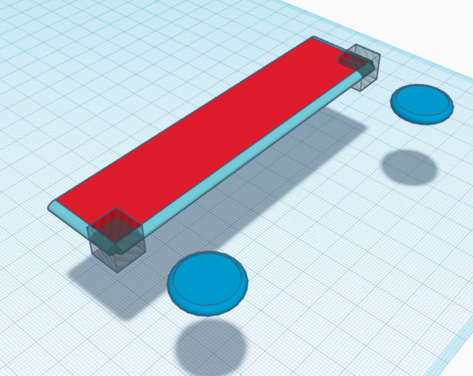
Everything else is just a repetition of the techniques outlined above. In order to merge the floor with the corner pieces with the cylindrical bottoms, you just use two overlapping rectangles. It’s important that your floor extends to the middle of the wall. This is so that it will not extend past the apex of the curve.
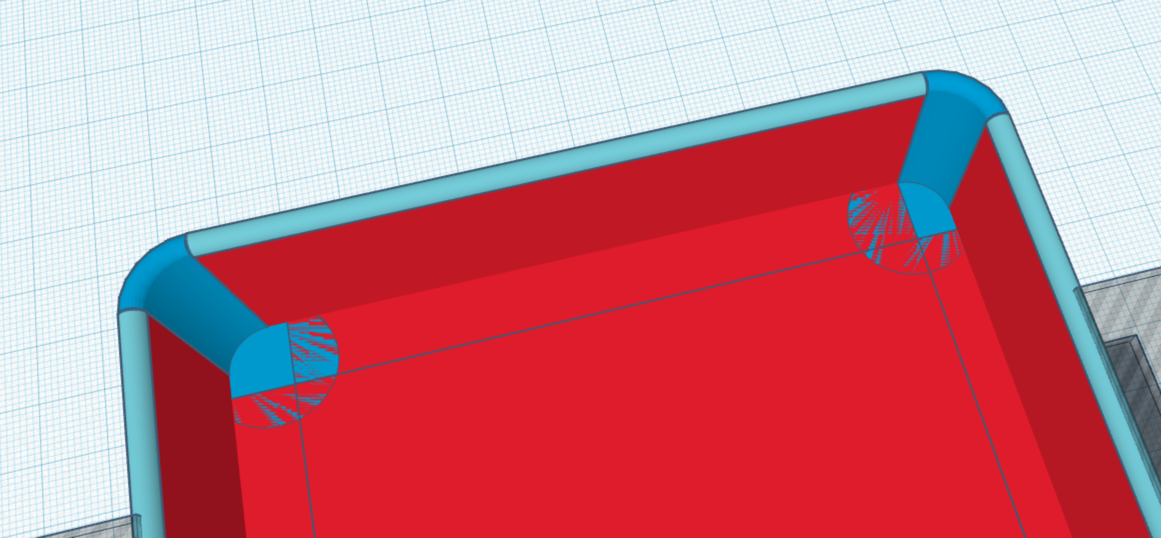
You may notice that mine are not placed identically relative to each corner. The way my walls are constructed it doesn’t matter, and the resulting gaps are hidden.
A Template For The Leather
I wanted a nice fit for the leather insert. In order to make this I took the final model for the tray, and separated all the pieces. I combined everything except the floors, and then made that into a “hole”. I combined the floor pieces and then cut the hole out of them. This left weird corners. So, I grabbed the cylinder I had used to cut a vertical hole in the corner, converted it to a solid, and moved it, and a copy, into position on each corner that needed to be rounded.
Then I combined them. There was no need to make them taller. It was just easier to move around in Tinkercad if they weren’t the same height.
Now, this template is the exact dimensions of the floor. If you account for expansion of the filament during printing you’ve got a template that won’t fit into the tray because it’s micrometers too big.
This is ok for leather. I placed it on top of the leather I was going to cut, and then angled my blade at roughly a 45° angle towards the center of the piece. This gave me very thin leather at the top, and a bottom of the full thickness. The result is that when I set it into the tray the edges are a hair wider than the hole they’re going into, but they’re also very thin there. This exerts just enough pressure to hold the leather in place without any adhesive required.
The leather I’ve chosen is very soft. This is beneficial in such a small tray because it absorbs most of the impact of the dice. They stop rolling almost instantly, which is good, because they have very little space to roll in this tiny tray.
Conclusion
That’s it. I hope this helps save you from the hours it took me to figure all this out. If you find this helpful, or confusing, please drop a line to me on mastodon at @masukomi@connectified.com or drop me an email at masukomi@masukomi.org.